Views: 0 Author: Site Editor Publish Time: 2026-09-02 Origin: Site
Stricter maritime emission regulations, specifically IMO Tier III, and the demand for higher onboard energy efficiency force vessel owners to rethink marine power systems. Selecting an undersized, oversized, or technologically mismatched marine generator results in mechanical failures, excessive fuel consumption, compliance penalties, and operational downtime at sea. Moving beyond basic wattage estimates requires a rigorous evaluation of your vessel’s true electrical load, fuel architecture trade-offs, operating environment durability, and long-term maintenance realities. Relying on outdated sizing methods leaves modern vessels underpowered during peak operational phases or suffering from mechanical degradation due to chronic under-loading. This guide provides a technical framework for selecting the optimal marine power solution. We will walk you through load calculations, architecture selection, and integration strategies to ensure your vessel maintains uninterrupted power while navigating complex regulatory landscapes.
Calculate with a Buffer: Always size your marine generator by calculating the total concurrent electrical load and adding a strict 20% power margin to prevent wet stacking and ensure peak performance.
Match Architecture to Application: The choice between fixed-speed reciprocating engines and variable-speed or turbine systems dictates your vessel's fuel efficiency and acoustic comfort.
Emissions Compliance is Non-Negotiable: Modern fleets are increasingly adopting the marine gas generator to meet stringent environmental mandates without sacrificing power density.
Defining a successful generator integration goes beyond matching kilowatt outputs to a spec sheet. An optimized marine power system must deliver uninterrupted power under peak load, ensure compliance with maritime emission standards, and maintain acceptable noise levels for passenger and crew comfort. The operational profile of the vessel dictates these success criteria. A commercial offshore support vessel prioritizes raw torque and continuous duty cycles. A luxury passenger ferry demands minimal acoustic intrusion and zero visible exhaust smoke.
The regulatory landscape acts as the primary catalyst for modernizing marine power. MARPOL Annex VI and the expansion of local Emission Control Areas (ECAs) strictly govern the allowable limits of nitrogen oxides (NOx) and sulfur oxides (SOx). These mandates drive the transition from heavy fuel oil and standard marine diesel to cleaner alternatives. Vessels operating within ECAs must utilize power systems capable of drastic emission reductions. Marine engineers now abandon legacy mechanical engines in favor of electronically controlled, clean-burning alternatives.
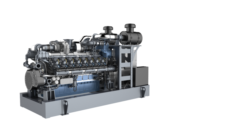
LNG and natural gas-powered generators are becoming the standard for commercial vessels, ferries, and large yachts seeking to balance power output with environmental compliance. A well-engineered gas generator eliminates particulate matter almost entirely. It significantly reduces NOx emissions compared to diesel counterparts. This transition allows fleets to operate legally in highly regulated waters. You also benefit from clean combustion characteristics that extend oil life and reduce internal engine wear.
Accurate sizing begins with a realistic audit of all onboard electrical needs. You must differentiate between systems that run constantly and those that draw high starting currents. Continuous loads include HVAC systems, refrigeration units, navigation electronics, and basic lighting. Intermittent loads encompass watermakers, heavy anchor winches, bow thrusters, and galley appliances. When auditing onboard systems, you must also account for non-linear loads from variable frequency drives and battery chargers, which can introduce harmonic distortion into the electrical grid.
The engineering failure often occurs when operators calculate based solely on running wattage. They ignore the massive inrush current required to start large induction motors. A 5kW bow thruster motor might require 15kW to 25kW for a few seconds during startup. This sudden draw can stall an undersized generator instantly. You must identify the locked rotor amps (LRA) of every heavy motor on board to understand the true transient load the alternator must support.
Matching the generator’s output to the vessel’s existing electrical infrastructure requires understanding phase and voltage requirements. Smaller vessels typically operate on single-phase power. Larger commercial ships and superyachts utilize three-phase systems to efficiently distribute heavy loads. Supplying a three-phase motor with single-phase power is impossible without complex conversion equipment. You must also account for the power factor, typically calculated at 0.8 for marine applications. This translates apparent power (kVA) into actual working power (kW).
Factoring in a capacity allowance for future vessel retrofits prevents premature obsolescence. Marine technology evolves rapidly. Adding gyroscopic stabilizers, upgraded dynamic positioning systems, or expanded refrigeration capacity will drastically alter your load profile. Building a forward-looking power margin into your initial calculations ensures the vessel can accommodate these upgrades. You avoid requiring a complete engine room overhaul later.
Operating a generator at extreme ends of its capacity spectrum introduces severe mechanical risks. Running a unit at less than 30% capacity causes incomplete combustion. This phenomenon, known as wet stacking, leads to unburned fuel and carbon buildup in the exhaust system. It causes glazing of the cylinder walls, oil dilution, and eventual loss of compression. Conversely, operating continuously at maximum capacity degrades engine lifespan. It increases thermal stress on the alternator windings and leaves no reserve for sudden load spikes.
Structuring the load so the generator runs consistently at 70% to 80% of its rated capacity represents the ideal operational sweet spot. This load profile ensures optimal combustion temperatures. It maximizes fuel efficiency and prevents carbon accumulation in the turbocharger and exhaust valves. The remaining 20% buffer serves a specific engineering purpose. It absorbs the transient spikes from heavy motor startups and provides a safety margin for unexpected operational demands. Maintaining this balance extends the service life of marine power generation equipment.
To properly execute a load analysis, follow these steps:
List every electrical device on the vessel and record its running wattage.
Identify all induction motors and multiply their running wattage by three to find the starting surge requirement.
Group the devices by operational phase, such as underway, at anchor, or emergency operations.
Calculate the highest concurrent load scenario based on realistic operational profiles.
Divide the highest concurrent load by 0.8 to establish the minimum required generator kW rating.
Fixed-speed systems represent the traditional approach to marine power. These units run at a constant RPM—typically 1500 RPM for 50Hz or 1800 RPM for 60Hz—regardless of the electrical load applied. The primary advantages include mechanical simplicity, proven reliability in heavy seas, and straightforward maintenance. The constant RPM means the engine burns a consistent baseline of fuel. It generates a continuous noise floor, even when the vessel draws minimal power.
Variable-speed systems utilize inverter technology to decouple engine RPM from the AC output frequency. The engine speeds up or slows down based directly on the real-time electrical demand. The alternator produces raw AC power, which is rectified to DC, and then inverted back to clean, stable AC power. This architecture results in significant fuel savings during low-load periods. It drastically reduces noise and vibration. Variable-speed units are highly favored in applications where loads fluctuate wildly throughout the day.
Piston-driven gas generators remain the backbone of continuous-duty marine applications. Traditional reciprocating engines offer massive torque, excellent load acceptance, and familiar maintenance protocols for marine engineers. They excel in environments where steady, heavy power generation is required for days or weeks at a time. The cast-iron blocks provide excellent thermal stability during long voyages.
Advanced turbine technology serves applications requiring an exceptionally high power-to-weight ratio. Gas turbines provide rapid startup times, minimal structural vibration, and an incredibly compact footprint relative to their megawatt output. They require specialized maintenance and handle transient loads differently than reciprocating engines. Turbines are unmatched for high-speed vessels and specialized platforms where every kilogram of engine weight impacts hull performance.
Selecting the appropriate cooling mechanism depends entirely on the vessel's hull design and operating environment. Heat exchanger cooling systems draw raw seawater into the vessel. They pass it through a heat exchanger to cool the closed-loop engine coolant, and expel it with the exhaust. This is highly efficient but vulnerable to intake blockages in shallow, debris-filled waters. You must regularly inspect and descale the heat exchanger core to maintain thermal efficiency.
Keel cooling utilizes external pipes mounted to the hull. This allows the surrounding ocean to cool the internal fluid without bringing raw water aboard. It eliminates raw water pump failures and strainer blockages. This setup is ideal for muddy or ice-prone environments. However, keel coolers are susceptible to marine growth and require specialized anti-fouling treatments during dry dock periods.
Comparison of Marine Generator Architectures
Architecture Type | Primary Advantage | Ideal Application | Operational Limitation |
|---|---|---|---|
Fixed-Speed Reciprocating | High reliability, simple maintenance | Continuous heavy loads, commercial shipping | Constant noise and fuel burn at low loads |
Variable-Speed Inverter | Fuel efficiency, low vibration at idle | Yachts, fluctuating hotel loads | Complex electronics, strict cooling needs |
Gas Turbine | Extreme power-to-weight ratio | High-speed ferries, naval vessels | Specialized maintenance, high air intake needs |
Evaluating the track record of heavy-duty equipment requires looking at continuous-run environments. The Jichai Gas Generator is engineered specifically for demanding maritime conditions where downtime is unacceptable. These units feature robust block designs and high-capacity lubrication systems. This allows for extended service intervals even under harsh loads. The mechanical architecture prioritizes accessibility. Shipboard engineers can perform routine maintenance and component replacements without requiring specialized diagnostic software.
This brand is an optimal fit for commercial fleets, dredgers, and offshore support vessels. These applications require high-torque, durable power generation capable of running heavy winches, dynamic positioning thrusters, and continuous industrial loads. The straightforward mechanical servicing ensures that repairs can be executed at sea. You maintain operational continuity during extended voyages without relying on shore-based technical support.
The integration of French marine engineering heritage with modern gas combustion technology defines the performance profile of the Weichai Baudouin Gas Generator. These systems meet the most stringent global emission standards while delivering uncompromising power density. The advanced electronic control units optimize the air-fuel mixture in real-time. This ensures clean burns and rapid response to sudden load changes. The build quality incorporates high-grade marine alloys to resist saltwater corrosion.
Large yachts, passenger ferries, and expedition vessels benefit immensely from this architecture. These vessels need a precise balance of robust power output to run extensive hotel loads and strict emissions compliance to enter protected marine reserves. The global service network availability ensures that parts and certified technicians can be sourced regardless of the vessel's port of call. This minimizes downtime during international transits.
Adapting aerospace-derived technology for marine environments provides unique engineering advantages. The AECC Gas Turbine Generator focuses entirely on maximizing power density. By utilizing rotary turbine stages rather than heavy reciprocating pistons, these generators deliver massive kilowatt output in a fraction of the space and weight of traditional engines. The continuous rotational movement eliminates the low-frequency structural vibrations typically associated with large diesel or gas engines.
This technology is the definitive choice for high-speed ferries, naval applications, or specialized commercial vessels where engine room space is severely limited. When hull dynamics dictate strict weight reduction to achieve target speeds, the turbine architecture provides the necessary electrical power without the parasitic weight penalty of a cast-iron engine block. The modular design also allows for rapid swap-outs during major overhaul periods.
Spatial planning in a marine engine room extends far beyond measuring the physical dimensions of the generator casing. You must factor in the required clearance for routine maintenance. Marine engineers need unobstructed access to perform oil changes, replace primary and secondary fuel filters, inspect raw water impellers, and service the heat exchanger core. Installing a generator flush against a bulkhead might save space initially but forces a complete engine removal for basic servicing later. Classification societies mandate specific clearance zones around rotating machinery for safety and maintenance access.
Calculating the required intake air for combustion and exhaust routing is critical to prevent engine room overheating. A generator consumes massive volumes of air. If the engine room ventilation cannot supply this volume, a vacuum effect occurs. This starves the engine of oxygen, drastically reduces power output, and increases exhaust gas temperatures (EGT). Ambient engine room temperatures must be controlled. If the intake air is too hot, its density decreases, leading to inefficient combustion. Proper exhaust routing, utilizing insulated dry stacks or water-injected wet exhausts, ensures toxic gases and intense heat are safely expelled from the vessel.
Acoustic management directly impacts the quality of life onboard. Evaluating the effectiveness of factory sound shields versus custom engine room acoustic insulation is a necessary step. Factory enclosures attenuate specific frequencies generated by the engine block and alternator. In luxury applications or passenger vessels, additional lead-lined acoustic foam on the engine room bulkheads is required. This prevents airborne noise from reaching accommodation spaces.
Structural vibration transfer to the hull must be intercepted at the source. The necessity of double-resilient mounts cannot be overstated. These mounts isolate the generator base frame from the vessel's stringers, absorbing low-frequency vibrations. Flexible exhaust bellows and braided stainless steel fuel line connections are mandatory. They prevent rigid pipes from fracturing under engine movement and stop vibration from traveling through the plumbing infrastructure into the hull.
Standard industrial generators will disintegrate in a marine environment. Ensuring the unit meets strict marinization standards is non-negotiable. The generator must feature water-cooled exhaust manifolds to keep surface temperatures below the ignition point of engine room fumes. Marine alternators should feature Class H insulation and a minimum IP23 rating to withstand engine room humidity. Corrosion-resistant alloys, such as cupronickel for heat exchanger tubes and specialized epoxy coatings for the alternator housing, are required to survive high-salinity air. Marine-grade wiring harnesses with tinned copper conductors and sealed connectors prevent moisture ingress and electrical shorts. This ensures the control systems remain functional in damp conditions.
Integrating a modern power system requires rigorous planning to avoid operational failures. One of the primary risks involves mismatched communication protocols between the generator and the vessel's existing infrastructure. Modern marine generators rely heavily on electronic control units to monitor engine health, load distribution, and fault codes. Ensuring the generator’s ECU offers seamless NMEA 2000 or J1939 CAN bus integration is vital. This compatibility allows the generator to communicate directly with the vessel’s central power management system. It enables automated load shedding, remote diagnostics from the bridge, and synchronized parallel operation if multiple generators are installed.
A failure in integration often results in the generator operating in isolation. The crew must manually intervene during load spikes or fault conditions. Proper integration allows the power management system to automatically start a secondary generator when the primary unit reaches 85% load. This ensures uninterrupted power. Testing these communication handshakes during the commissioning phase prevents catastrophic blackouts during active sea duty. During commissioning, mandate a full load bank test. This verifies the generator can sustain 100% nameplate capacity for at least two hours without exceeding thermal limits.
The operational viability of any marine generator is inextricably linked to its supply chain. Selecting a highly advanced power system is useless if replacement parts cannot be sourced in your operational theater. Ensuring the chosen brand has a robust parts distribution network and certified technicians in the specific global regions where the vessel will operate is a critical evaluation metric. Commercial vessels operating on tight schedules cannot afford to wait weeks for a proprietary sensor or a replacement ECU to be shipped across the globe.
Vessel operators must verify the availability of critical wear items at major ports along their intended routes. These include raw water pumps, heat exchanger gaskets, specialized filters, and fuel injectors. Establishing a comprehensive onboard spares kit mitigates the risk of supply chain bottlenecks. Tailor this kit specifically to the engine's maintenance schedule and the vessel's isolation level to keep the vessel operational in remote waters.
To ensure a smooth installation and long-term operation, verify the following with your supplier:
Availability of comprehensive wiring diagrams and CAN bus integration protocols.
Lead times for major replacement components like alternators and turbochargers.
Warranty terms regarding self-performed maintenance while at sea.
Access to remote technical support for ECU troubleshooting.
Hire a certified marine electrician to perform a comprehensive load analysis, documenting all continuous draws and transient motor startup surges.
Request detailed installation clearance diagrams from manufacturers to verify the generator fits within your engine room while maintaining mandatory maintenance access zones.
Verify the communication protocols of the selected generator to guarantee seamless integration with your vessel's existing power management system.
Procure a customized onboard spare parts kit that includes raw water impellers, fuel filters, and heat exchanger gaskets before departing on extended voyages.
A: Calculate the total wattage of all systems that will run concurrently. Factor in the massive startup surge of electric induction motors, such as air conditioning compressors and watermakers. Add a strict 20% safety margin to this total. This ensures the generator runs efficiently without being overloaded during sudden power demands.
A: Marine generators are specifically marinized to survive harsh, high-salinity environments. They feature water-cooled exhaust manifolds to keep engine room temperatures safe. They also utilize specialized corrosion-resistant coatings, tinned wiring harnesses, and marine-specific cooling systems like cupronickel heat exchangers or keel coolers.
A: Yes, provided they are marine-certified by recognized classification societies. They must be installed with compliant, high-capacity ventilation, continuous gas detection systems, and double-walled piping. This ensures any potential leaks are safely contained and vented away from ignition sources.
A: Fixed-speed generators run at a constant RPM regardless of the electrical load, offering simplicity and reliability. Variable-speed generators use inverters to adjust their RPM based on real-time power demand. This significantly reduces fuel consumption and noise during low-load periods.
A: Wet stacking occurs when a generator consistently runs at less than 30% of its rated capacity. The engine fails to reach optimal operating temperature. This results in unburned fuel and carbon accumulating in the exhaust system, which eventually glazes cylinder walls and degrades performance.
A: Keel cooling utilizes a closed-loop system with pipes mounted on the outside of the hull. It uses the surrounding ocean water to cool the engine fluid. It is preferred in muddy, shallow, or ice-filled waters because it eliminates the need for raw water intake pumps and strainers, which easily clog with debris.