Views: 0 Author: Site Editor Publish Time: 2026-09-21 Origin: Site
Unplanned downtime costs mission-critical facilities thousands of dollars per minute. Data centers, healthcare facilities, and continuous manufacturing plants cannot afford a momentary lapse in power. A sudden outage ruins production batches, compromises patient life-support systems, and causes data loss. Utility grids remain inherently vulnerable. Severe weather events, aging infrastructure, and capacity limits frequently trigger rolling blackouts and unexpected grid failures. Facilities require a fail-safe mechanism that assumes electrical loads instantaneously without disrupting sensitive equipment or overarching operational continuity.
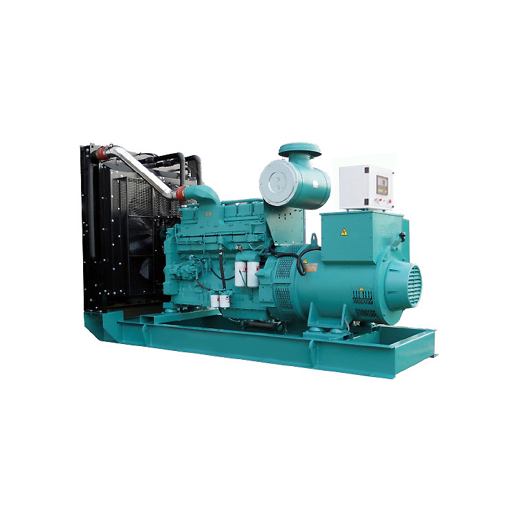
A standby diesel generator serves as the foundational component of a synchronized emergency power supply system. It acts as far more than just a mechanical engine. It provides an energy-dense defense against grid instability. By integrating with facility switchgear, uninterruptible power supplies, and transfer switches, this system supports critical loads when uptime is non-negotiable. You must understand the underlying architecture, sequence of operations, and precise sizing principles to ensure continuous power.
Seamless Load Assumption: Standby diesel generators work in tandem with Uninterruptible Power Supplies (UPS) and Automatic Transfer Switches (ATS) to ensure zero power interruption to critical infrastructure.
Precision Sizing is Mandatory: Accurate kW/kVA load calculations must account for transient response, motor starting currents, and step-loading capabilities to prevent generator stalling or voltage dips.
Configuration Dictates Viability: Selecting specific enclosures (such as a silent diesel generator) and proven engine blocks (like a Cummins diesel generator or Perkins diesel generator) depends heavily on site constraints, noise ordinances, and load profiles.
Maintenance Drives Reliability: Strict Operations & Maintenance (O&M) protocols, including fuel polishing and load bank testing, mitigate risks like wet stacking and fuel degradation.
You must identify exactly what qualifies as a critical load before designing any backup power system. Facilities divide electrical loads into distinct categories to manage power effectively during an emergency. We look at the panel schedules and separate the circuits. Life-safety loads include fire pumps, emergency lighting, and medical life-support equipment. These require immediate power restoration by law. Critical loads encompass servers, telecommunications gear, and cleanroom HVAC systems. Non-essential loads, such as perimeter lighting or breakroom appliances, often shed during an outage. Shedding non-essential loads preserves generator capacity for the equipment that truly matters.
The power chain hierarchy dictates how electricity flows through a facility under normal and emergency conditions. We build this hierarchy to isolate faults and ensure multiple layers of redundancy.
The primary utility grid feeds the main distribution panel through a step-down transformer.
An Automatic Transfer Switch (ATS) continuously monitors this utility feed for voltage drops or phase loss.
The Uninterruptible Power Supply (UPS) sits downstream from the ATS, positioned directly between the power source and the sensitive critical loads.
The diesel generator waits in reserve, connected to the emergency side of the ATS.
Safeguarding the generator itself remains a primary engineering concern. You must protect the emergency power supply from the exact same hazards that caused the grid failure. Advanced switchgear and electrical fault protection prevent power surges from damaging the alternator. Physical security requires heavy civil work. We install concrete bollards filled with rebar to prevent vehicle impacts. We pour elevated concrete pads to keep the equipment above historical flood lines and prevent water ingress. We enclose the system behind secure fencing to deter tampering and unauthorized access.
Regulatory frameworks dictate strict performance standards for emergency power systems. NFPA 110 and ISO 8528 outline specific operational requirements. NFPA 110 categorizes systems by Level, Class, and Type. Level 1 systems apply where failure could result in loss of human life. Class dictates the minimum runtime in hours without refueling. A Class 48 system requires 48 hours of on-site fuel storage. Type dictates the maximum time allowed for the generator to start and assume the load. Life-safety systems typically require a Type 10 response. The system must restore power within exactly 10 seconds.
When utility power fails, a highly coordinated sequence of events unfolds automatically. The ATS serves as the brain of the transition process. It continuously monitors the utility voltage across all three phases. It detects anomalies, severe voltage sags, or total power loss. To prevent starting the engine during a momentary voltage flicker, the ATS utilizes a Time Delay Engine Start (TDES) timer. We usually set this timer between 1 and 3 seconds. Once the timer expires and the failure is confirmed, the ATS sends a low-voltage start signal to the generator control panel.
The UPS plays a vital bridging role during this transition. It takes several seconds for a heavy-duty engine to crank, ignite, and accelerate to synchronous speed. During this window, the UPS provides immediate, conditioned battery power to sensitive electronics. This ride-through capability prevents servers from crashing, keeps medical monitors active, and maintains programmable logic controllers on manufacturing floors. Without the UPS, the 10-second gap would cause a hard reset of all facility electronics.
As the engine accelerates, the alternator and automatic voltage regulator (AVR) work aggressively to stabilize the electrical output. The engine governor injects precisely metered fuel to lock the engine speed at the required RPM. We run these engines at 1800 RPM for 60Hz applications or 1500 RPM for 50Hz applications. Simultaneously, the AVR adjusts the excitation field in the alternator to build and maintain the correct voltage. The ATS continuously monitors the generator output. It waits until the voltage and frequency stabilize within acceptable tolerances.
Once the output stabilizes, the ATS executes the transfer. It physically disconnects the facility from the dead utility grid and connects it to the generator feed. This mechanical interlock prevents backfeeding deadly voltage onto utility lines, protecting linemen working on the grid. The critical load now transfers from the UPS batteries to the generator. When utility power eventually returns, the ATS observes a Time Delay Return to Normal (TDRN) timer. We set this for 15 to 30 minutes to ensure the grid is stable before transferring the load back. After the transfer, the generator enters a cool-down cycle for five minutes before shutting down.
Accurate sizing prevents system failure during an emergency. Undersizing leads to engine stalling, severe voltage drops, and overheating. Oversizing leads to mechanical inefficiencies and premature engine wear. You must calculate total power requirements using both kW (real power) and kVA (apparent power). Real power represents the actual work performed by the equipment. Apparent power accounts for the total power drawn from the generator, including reactive power used to magnetize motors. The ratio between kW and kVA is the Power Factor. We calculate industrial generators at a 0.8 power factor.
You must distinguish clearly between steady-state running loads and peak starting loads. Motors, HVAC compressors, and large water pumps draw massive inrush currents when starting. This starting current, known as Locked Rotor Amps (LRA), can be up to six times higher than the normal running current. If multiple large motors start simultaneously, the sudden kVA demand overwhelms the alternator. The magnetic field collapses, and the voltage plummets. We use step-loading sequences to start large motors one at a time, allowing the generator to recover between each step.
Transient response dictates how the system handles block loading. Block loading occurs when large electrical loads apply suddenly in a single step. The generator must absorb these loads without severe voltage dips or frequency drops. ISO 8528 defines specific performance classes based on how quickly the voltage and frequency recover after a sudden load change. Data centers require G3 or G4 performance. If the frequency drops too far during a load step, the UPS interprets the generator power as unstable. It rejects the feed and continues draining its batteries until they die.
Modern IT equipment, LED lighting, and variable frequency drives (VFDs) create significant harmonic distortion. These non-linear loads draw current in abrupt pulses rather than a smooth sine wave. This distorts the electrical waveform, pushing excess heat into the alternator windings and the neutral wire. To mitigate this, engineers oversize the alternator relative to the engine. We specify alternators with a 2/3 pitch winding. This physical winding configuration cancels out third-order harmonics and prevents dangerous neutral current buildup.
Load Type | Equipment Examples | Impact on Generator Sizing |
|---|---|---|
Linear / Resistive Loads | Incandescent lighting, resistive heating elements | Straightforward kW calculation. Minimal harmonic distortion. Power factor is typically 1.0. |
Inductive Motor Loads | HVAC compressors, water pumps, elevators, chillers | High starting kVA (inrush current). Requires robust transient response and alternator oversizing. |
Non-Linear Loads | Servers, UPS systems, VFDs, switching power supplies | Generates severe harmonic distortion. Requires 2/3 pitch stators and advanced AVRs. |
Life-Safety Loads | Fire pumps, emergency egress lighting, smoke evacuation fans | Requires strict adherence to NFPA 110 Type 10 response times. Must assume load within 10 seconds. |
Site constraints heavily influence equipment selection and physical configuration. Urban environments, office parks, and hospitals enforce strict noise ordinances. These sites necessitate a silent diesel generator. Standard open-skid generators produce noise levels exceeding 100 dB(A), which is deafening. Acoustic enclosures utilize heavy-gauge steel, sound-attenuating rock wool, vibration isolators, and engineered air baffles to reduce noise. A high-quality enclosure drops sound pressure levels to 70 dB(A) at 7 meters. You must balance acoustic attenuation with the enclosure footprint and airflow requirements. Restricting airflow to trap sound waves increases internal temperatures. This requires larger cooling fans and oversized radiators to prevent the engine from overheating.
Evaluating Tier-1 engine manufacturers ensures long-term reliability and parts availability. The engine block is the mechanical heart of the system. Selecting a proven brand mitigates operational risk.
A Cummins diesel generator offers a highly integrated approach. Cummins manufactures the engine, alternator, and proprietary control systems in-house. This single-source design delivers exceptional block load acceptance and fast communication between components. They maintain a highly responsive global service network for rapid parts deployment.
A Perkins diesel generator provides exceptional engine durability and fuel efficiency. Packagers frequently use Perkins engines to build custom-configured generator sets. They offer excellent integration flexibility, making them ideal for specialized industrial applications and tight footprint constraints.
Caterpillar systems excel in heavy-duty deployments. They deliver high performance in extreme environmental conditions, from high-altitude mining operations to extreme cold-weather installations. Their engines feature massive displacement and high torque output.
Modular infrastructure allows for rapid deployment and advanced redundancy. Instead of installing a single massive 2000kW generator, facilities often parallel four 500kW units. This creates an N+1 redundancy configuration. If one unit fails to start or requires maintenance, the remaining three units still support the critical load. Paralleling switchgear synchronizes the voltage, frequency, and phase angle of all units before connecting them to a common bus. Modular setups enable scalability. As facility energy demands grow, you add another module to the paralleling bus rather than replacing the entire system.
Diesel fuel management remains a primary operational risk for any standby system. Diesel fuel degrades chemically over time. Asphaltenes agglomerate, turning the fuel dark and creating sludge. Temperature fluctuations inside the storage tank cause condensation, leading to water accumulation at the bottom. This water breeds microbial growth. During an emergency run, this sludge and biomass get sucked into the fuel lines. They instantly clog primary and secondary fuel filters, starving the engine of fuel. We install automated fuel polishing systems to mitigate this. These systems cycle the fuel through particulate filters, water separators, and UV biocides on a weekly basis, ensuring the fuel remains pristine.
Running a heavy-duty engine on light loads creates severe mechanical risks. Operating below 30% of the rated capacity leads to wet stacking. Diesel engines rely on high combustion temperatures to expand the piston rings and seal the cylinder. When running lightly loaded, the engine runs cold. Unburned fuel and lubricating oil bypass the rings and enter the exhaust manifold. This creates a thick, dark substance that coats the turbocharger and exhaust piping. Wet stacking reduces engine efficiency, increases emissions, and poses a significant exhaust fire hazard. Routine load bank testing prevents this. A load bank provides an artificial electrical load, forcing the engine to work at 80% to 100% capacity. This burns off carbon deposits and verifies the system can handle its rated output.
Implement a strict Operations & Maintenance framework to guarantee reliability. Standby systems sit idle for months, making hidden failures highly probable without active maintenance.
Conduct regular fluid sampling for engine oil and coolant. Spectrometric oil analysis detects microscopic wear metals, providing early warning of bearing or cylinder wear.
Perform weekly battery testing. Battery failure is the number one cause of generators failing to start. Check specific gravity, clean terminals, and verify the float voltage on the battery charger.
Inspect block heaters daily. Block heaters keep the engine coolant warm, ensuring the oil remains viscous and the engine starts immediately in cold weather.
Schedule comprehensive simulated outages annually. Drop the main utility breaker and force the entire system to perform a real-world transition under facility load.
Environmental regulations dictate strict emissions compliance for diesel engines. The EPA Tier 4 Final standards require advanced exhaust aftertreatment systems to reduce nitrogen oxides and particulate matter. These systems utilize Selective Catalytic Reduction and Diesel Particulate Filters. Facilities in strict air quality jurisdictions may require Tier 4 compliance even for emergency-only units.
Schedule a comprehensive site power audit to identify all critical, life-safety, and non-essential loads on your panel schedules.
Conduct a professional load study using power quality meters to capture peak inrush currents and harmonic distortion levels from your existing equipment.
Consult a licensed power systems engineer to specify precise kW/kVA requirements and determine the necessary alternator oversizing for your facility.
Evaluate your site footprint to determine enclosure limitations, fuel storage capacity, and exhaust routing requirements before purchasing equipment.
Establish a contract for automated fuel polishing and semi-annual load bank testing immediately after commissioning your new system.
A: A properly maintained system detects a utility failure, starts the engine, and assumes the critical load within 10 seconds. This rapid response meets strict life-safety codes for hospitals and commercial facilities. The UPS bridges the power gap during these crucial seconds to prevent electronics from resetting.
A: Standby power ratings define the maximum power available for a limited duration during a utility outage. Standby units do not have overload capability. Prime power ratings indicate the generator can supply continuous power for an unlimited number of hours, acting as the primary electricity source rather than a backup.
A: The UPS provides instantaneous battery power the millisecond the grid fails, preventing server crashes and data corruption. However, UPS batteries drain quickly. The generator provides long-term, continuous power. The UPS keeps the servers running just long enough for the generator to start, stabilize, and take over.
A: Facilities should conduct weekly visual inspections and no-load engine runs. Monthly testing should include running the generator under a load of at least 30% capacity. Annual comprehensive maintenance involves fluid changes, filter replacements, and a multi-hour load bank test to verify peak performance.
A: These units feature specialized acoustic enclosures. The enclosures utilize sound-absorbing rock wool, vibration isolators, and engineered air baffles. These components redirect noise and restrict sound waves from escaping, allowing the equipment to meet strict urban or residential noise ordinances without restricting necessary cooling airflow.
A: Wet stacking occurs when a diesel engine runs on light loads, causing unburned fuel and carbon to accumulate in the exhaust system. It reduces engine efficiency, damages turbochargers, and poses a fire hazard. Prevent it by performing routine load bank testing to burn off deposits at high temperatures.