Views: 0 Author: Site Editor Publish Time: 2026-08-20 Origin: Site
Unplanned downtime drains revenue rapidly. Executing a commercial-grade power backup project involves immense logistical complexity. Installing a commercial unit is never a simple plug-and-play scenario. Facility managers must enforce strict adherence to load calculations, site preparation, environmental compliance, and OEM guidelines. Skipping these steps invites catastrophic system failure, voids warranties instantly, and triggers severe regulatory fines. A standard diesel generator requires precise integration with existing electrical infrastructure to function safely during grid failures.
We present a structured, evidence-based approach to power system deployment. You will learn how to evaluate site requirements accurately and navigate municipal zoning laws. We explain how to select the correct capacity based on actual facility demand rather than rough estimates. Finally, we guide you through executing a compliant, risk-mitigated installation that protects both your personnel and your capital investment.
Accurate load calculation (AMPS, voltage, and phase) dictates the entire installation scope and prevents premature equipment failure.
Site preparation requires balancing physical footprint, exhaust routing, acoustic treatments, physical security, and strict local zoning laws.
The total cost of installation extends significantly beyond the unit price, encompassing specialized rigging, electrical integration (ATS), site excavation, and weatherization.
Selecting the right equipment requires matching specific facility load profiles with verified engine capabilities and compliance standards.
Strict adherence to manufacturer installation manuals and OSHA safety protocols is non-negotiable to protect personnel and equipment warranties.
Understanding the differences between continuous, prime, and standby power ratings forms the foundation of any successful installation. Standby ratings apply to units intended to supply emergency power for the duration of a utility outage. Prime power acts as the primary source of electricity for off-grid operations, allowing for variable loads over unlimited hours. Continuous power ratings apply to units running at a constant, unvarying load indefinitely. Applying a standby-rated unit to a continuous power application causes severe engine wear and thermal failure.
Calculating the total facility load requires differentiating starting wattage (surge) from running wattage. Industrial motors, HVAC compressors, and heavy manufacturing equipment require massive surge currents to overcome initial inertia. If you size the unit based solely on running wattage, the alternator will stall, and the main breaker will trip immediately upon load transfer. Engineers must calculate the power factor, typically 0.8 for three-phase systems, to convert kilovolt-amps (kVA) to kilowatts (kW) accurately.
Motor Starting Multipliers Reference
Equipment Type | Running Wattage Multiplier | Surge Duration |
|---|---|---|
Standard HVAC Compressors | 3x to 4x | 1-3 seconds |
Industrial Conveyor Motors | 4x to 6x | 2-5 seconds |
Commercial Refrigeration | 3x | 1-2 seconds |
Server Rack Power Supplies | 1.5x | < 1 second |
Factor in a 20-25% capacity buffer for future facility expansion and scalability. Facilities grow over time. New production lines get added, and server racks expand. A capacity buffer prevents immediate obsolescence. Furthermore, diesel engines operate most efficiently at 70-80% of their rated load. Running a unit constantly at 100% capacity accelerates component degradation, while running below 30% causes unburned fuel buildup in the exhaust system.
Selecting and sizing the Automatic Transfer Switch (ATS) depends entirely on the facility's existing electrical infrastructure. The ATS senses utility failure, commands the engine to start, and transfers the load once voltage and frequency stabilize. Size the ATS according to the main breaker amperage. You must decide between open transition (break-before-make) and closed transition (make-before-break) switches, depending on whether your facility can tolerate a momentary power interruption during the return to utility power.
Evaluate voltage requirements meticulously. Small commercial facilities typically use 120/240V single-phase power. Large industrial sites, manufacturing plants, and data centers demand 277/480V three-phase configurations. Matching the output voltage to the existing electrical panel is mandatory. Mismatched voltages destroy sensitive facility equipment instantly. Ensure the alternator windings are configured correctly at the factory before delivery.
Define the grounding and bonding protocols required to ensure National Electrical Code (NEC) compliance. Proper grounding prevents ground faults and guarantees personnel safety during maintenance. Drive copper ground rods deep into the soil to achieve a low-resistance path to earth. Bond the neutral to the ground at the correct system point. If the ATS switches the neutral pole, the unit acts as a separately derived system and requires its own grounding electrode system.
Engineering the concrete mounting pad requires precise geotechnical calculations. Engineers must determine the soil bearing pressure before pouring concrete. The pad must support the wet weight of the unit—including full fuel tanks and coolant—without settling or cracking. The concrete pad should extend a minimum of 12 inches beyond the unit's physical dimensions. Use vibration isolation mounts between the steel skid and the concrete to prevent structural damage and reduce low-frequency acoustic transmission.
Concrete Pad Pouring Sequence
Excavate the designated area to a depth of at least 12 inches below grade.
Compact the subgrade soil using a vibratory plate compactor to achieve 95% compaction density.
Install a 4-inch layer of crushed gravel base to ensure proper drainage beneath the slab.
Construct the wooden formwork, ensuring all corners are perfectly square and level.
Place #4 rebar in a grid pattern, elevating it on chairs to sit in the middle third of the concrete depth.
Pour 4000 PSI concrete, vibrating the mix to eliminate air pockets, and apply a smooth trowel finish.
Allow the concrete to cure for a minimum of 7 to 14 days before placing heavy equipment on the pad.
Define the mandatory clearance perimeters required for safe maintenance access. Technicians need unobstructed space to pull air filters, replace batteries, and access control panels. Optimal airflow requires clear paths for the radiator fan to push hot air away from the enclosure. Fire codes strictly dictate minimum distances from combustible walls, building overhangs, and ventilation intakes.
Physical security measures protect the asset from environmental and human threats. Install heavy-duty anti-ram bollards around the perimeter to prevent accidental vehicle impacts from delivery trucks. Erect security fencing to deter unauthorized access. Use lockable weatherproof enclosures to protect control interfaces and fuel fill ports from vandalism or tampering.
Acoustic regulations dictate enclosure selection. Local zoning laws heavily restrict decibel levels at the property line, especially in mixed-use or residential-adjacent commercial zones. Standard weather enclosures provide minimal sound dampening. Level 1 acoustic enclosures reduce noise for basic commercial applications. Level 2 and Level 3 enclosures utilize thick acoustic foam, baffled air intakes, and critical-grade exhaust silencers to meet stringent hospital or urban noise ordinances.
Compliance standards for exhaust routing and emissions control require strict oversight. Direct exhaust gases away from building air intakes, operable windows, and pedestrian walkways. Depending on your region, Environmental Protection Agency (EPA) regulations may require Tier 4 Final compliance, necessitating Diesel Exhaust Fluid (DEF) systems and Diesel Particulate Filters (DPF) to scrub emissions before they exit the stack.
Address cold-weather preparations thoroughly. Diesel engines struggle to ignite compressed cold air. Install thermostatically controlled engine block heaters to maintain coolant temperature. Add battery warmers to ensure maximum cranking amps during freezing conditions. Utilize motorized louvers on indoor installations to trap heat when the engine is idle and open automatically upon startup to provide combustion air.
Compare the operational trade-offs between sub-base fuel tanks and external, standalone tanks. Sub-base tanks sit directly beneath the engine skid, saving valuable site footprint. They typically hold enough fuel for 24 to 48 hours of runtime. External standalone tanks hold massive volumes for extended runtimes exceeding 72 hours, but they require dedicated real estate, underground trenching, and mechanical transfer pumps.
Regulatory requirements mandate secondary spill containment. Fire marshals and environmental agencies require containment basins capable of holding 110% of the primary tank's volume. This prevents catastrophic soil contamination during a rupture. Plan logistical access for commercial fuel delivery trucks. The fill port must be easily accessible for a heavy tanker truck without blocking facility traffic.
Fuel quality management dictates long-term reliability. Diesel fuel degrades, absorbs water, and breeds microbes over time. Order winter-blend diesel for cold regions to prevent waxing. Add anti-gel chemicals before winter sets in. Implement biocide treatments and schedule annual fuel polishing to remove sludge, ensuring the engine receives clean, combustible fuel during an emergency.
Medium-scale manufacturing, retail complexes, and commercial real estate facilities require robust, predictable backup power. The operational profile for these sites involves moderate loads, such as emergency lighting, security systems, commercial refrigeration, and basic HVAC operations. Space constraints often dictate equipment choices, requiring a balance between power output and physical footprint.
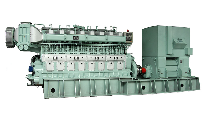
Evaluate the CSI Ningdong N210 Diesel Generator Set as a benchmark for these applications. It balances moderate load requirements with strict footprint constraints. This unit delivers efficient power without overwhelming site logistics. It provides fast transient response times, ensuring that sensitive retail point-of-sale systems and commercial servers do not reboot during the transition from utility to backup power.
Data centers, hospitals, and heavy manufacturing plants operate under rigorous demands. A momentary power lapse in these environments causes severe operational disruption, data loss, or life-safety hazards. These facilities require continuous or high-tier standby power capable of accepting massive step-loads instantly. The equipment must handle heavy harmonic distortion from variable frequency drives (VFDs) and UPS systems.
Analyze the deployment of the CSI Ningdong G300 Diesel Generator Set for these environments. It handles high-demand reliability effortlessly. It supports advanced load management protocols and integrates seamlessly with complex switchgear. Industrial sites rely on this tier of equipment to maintain mission-critical operations, utilizing its heavy-duty alternator windings to absorb voltage spikes and maintain frequency stability.
Extreme peak loads, critical infrastructure projects, and municipal water treatment plants require specialized engineering. These operations demand multi-megawatt parallel configurations. Multiple units sync together to form a localized microgrid. Paralleling provides absolute redundancy; if one engine requires maintenance, the others scale up to carry the critical facility load.
Assess the integration of the CSI Ningdong NL340 Diesel Generator Set for maximum output scenarios. It meets rigorous compliance standards and heavy industrial applications. Deploying this unit in a paralleled configuration ensures that massive inductive loads, such as industrial shredders or municipal water pumps, receive the necessary surge current without dragging down the system voltage.
Analyze the conceptual trade-offs between upfront equipment costs and long-term operational efficiencies. High-efficiency engines require a larger initial capital expenditure. However, they consume significantly less fuel per kilowatt-hour generated. They also feature hardened internal components that extend routine maintenance intervals. Lower fuel consumption rates and reduced service frequency reduce operational expenditure over a twenty-year lifecycle.
Installation Cost Factor Analysis
Cost Category | CapEx Impact | OpEx Impact | Mitigation Strategy |
|---|---|---|---|
Equipment Sizing | High (Larger kW = Higher Price) | Moderate (Fuel consumption) | Perform precise load calculations to avoid oversizing. |
Acoustic Enclosures | High (Level 2/3 add significant cost) | Low | Verify local zoning laws before defaulting to Level 3. |
Fuel Storage Type | Moderate (Sub-base vs External) | High (Fuel polishing, testing) | Match tank size to actual required runtime codes. |
Electrical Integration | High (ATS, Switchgear, Labor) | Low (Annual ATS testing) | Locate the unit close to the main electrical room. |
Identify frequently overlooked line items that inflate project budgets. Specialized rigging requires heavy machinery and experienced personnel. Crane rentals add substantial daily fees, especially if site access requires a high-tonnage crane to lift the unit over existing structures. Heavy freight logistics involve wide-load highway permits, police escorts, and specialized flatbed trailers.
Break down the secondary costs of site preparation. Permitting fees vary wildly by municipality and require stamped engineering drawings. Specialized electrical labor commands premium hourly rates for high-voltage terminations. Site excavation, trenching for underground conduit, and pouring structural concrete require heavy earthmoving equipment. Physical security installations, including bollards and fencing, add material and labor expenses.
Evaluate the long-term value of OEM warranties versus the cost of third-party preventative maintenance contracts. Factory coverage protects against catastrophic internal defects and casting failures. Factory-certified technicians carry specialized diagnostic software required to read proprietary engine codes. While third-party vendors might offer lower hourly rates, they often lack the proprietary tools necessary to execute deep software diagnostics or warranty-approved repairs.
Miscommunication between the equipment supplier, electrical engineer, and general contractor ruins timelines. The electrical engineer designs the system. The general contractor pours the pad and trenches the conduit. The equipment supplier delivers the unit. The electrical contractor pulls the wire. Disconnects between these parties cause costly rework, such as conduit stub-ups missing the enclosure entry points.
Provide a framework for defining clear scopes of work and liability at each stage. Document every handoff meticulously. Hold a mandatory pre-installation site meeting with all stakeholders. Emphasize the necessity of strict adherence to OEM installation manuals. Third-party contractors often attempt to improvise exhaust routing or fuel piping. Improvisation voids warranties instantly. Follow the manual precisely.
Heavy rigging poses severe dangers to site personnel. Crane operations require strict safety protocols to prevent crushing accidents. Clear the drop zone entirely. Use certified lifting straps and spreader bars to prevent enclosure damage. Prevent site accidents through rigorous oversight and designated safety officers during the offloading phase.
Outline electrical safety standards during high-voltage integration. Arc flash mitigation requires specialized personal protective equipment (PPE), including flash suits and insulated gloves. Implement strict lockout/tagout (LOTO) procedures before opening any existing facility switchgear. Never allow technicians to work on live busbars. Verify zero energy state with calibrated multimeters before terminating cables.
Explain the critical necessity of load bank testing. You cannot validate performance by simply turning the engine on. A load bank applies an artificial electrical resistance to the system, simulating peak facility demand. You must prove the engine, alternator, and cooling system can handle full capacity for several hours without overheating or experiencing voltage drops before facility handover.
Proper commissioning identifies and mitigates the risk of wet stacking. Diesel engines must run hard to generate sufficient exhaust heat. Light loads cause unburned fuel and carbon to accumulate in the exhaust system. The initial break-in period requires high temperatures to seat the piston rings properly and burn off factory preserving oils.
Establish baseline protocols immediately after handover. Schedule regular fuel polishing to remove water condensation and sediment from the tank. Implement routine fluid analysis routines, taking oil and coolant samples to detect internal engine wear before components fail. Conduct weekly no-load ATS testing and monthly loaded runs to ensure day-one reliability is maintained throughout the equipment's lifespan.
Conduct a comprehensive facility load audit using data loggers to capture peak surge demands.
Finalize ATS sizing, transition type, and electrical schematics with a licensed engineer.
Review the OEM installation manual for specific clearance, mounting, and ventilation requirements.
Secure local zoning approvals, noise variance permits, emissions certifications, and building permits.
Determine the optimal site location to minimize conduit runs and exhaust nuisance.
Excavate the site and compact the subgrade soil to required bearing pressures.
Pour and cure the engineered concrete pad, ensuring vibration isolation mounts are pre-positioned.
Execute trenching for electrical conduit, control wires, and external fuel lines.
Install physical security barriers, including anti-ram bollards and perimeter fencing.
Coordinate crane sizing, rigging equipment, and traffic control for safe unit placement.
Mount, install, and wire the Automatic Transfer Switch into the facility's main distribution panel.
Establish proper grounding and bonding connections per NEC standards using driven copper rods.
Complete exhaust piping, ensuring thermal wraps are applied to prevent burn hazards.
Connect and verify fuel delivery systems, leak detection sensors, and secondary containment basins.
Wire and test weatherization kits, including engine block heaters and battery maintainers.
Perform comprehensive fluid checks (coolant, oil, fuel) and execute the initial start-up sequence.
Execute a 4-hour resistive load bank test and verify voltage and frequency stability under step-loads.
Simulate a utility power failure to test ATS automatic transfer and re-transfer sequences.
Train facility management on emergency shutdown procedures, basic diagnostics, and safety protocols.
Hand over all OEM manuals, warranty documentation, and baseline fluid analysis reports.
Engage a licensed electrical engineer to perform a comprehensive facility load audit and finalize ATS schematics.
Submit stamped structural and electrical drawings to the local municipality to secure zoning and building permits.
Request detailed technical specifications and acoustic data for shortlisted equipment models.
Schedule a mandatory pre-installation coordination meeting with your general contractor, electrical team, and rigging specialists.
A: Fire codes and NEC regulations typically dictate a minimum clearance of 5 feet from combustible walls and building openings. However, exhaust routing and local zoning laws often require greater distances. Always consult your local fire marshal and the OEM installation manual for specific clearance mandates to ensure optimal airflow and safety.
A: The concrete pad must extend at least 6 to 12 inches beyond the unit's physical footprint on all sides. Depth usually ranges from 6 to 8 inches, depending on soil stability and total equipment weight. An engineer must verify the concrete mix, PSI rating, and rebar requirements based on local seismic codes.
A: NEC standards require the system to be properly grounded to earth using driven copper rods. The neutral must be bonded to the ground at the correct point, depending on whether the system is configured as a separately derived system. This prevents ground faults, stabilizes voltage, and ensures personnel safety during operation.
A: Yes. An ATS is mandatory for seamless backup power integration. It continuously monitors utility power, automatically starts the engine during an outage, and safely transfers the facility load. It also isolates your system from the grid, preventing dangerous backfeeding that could electrocute utility workers repairing the lines.
A: The physical installation and mechanical hookup usually take one to two weeks. However, the entire process—including engineering, permitting, concrete curing, and utility coordination—can span two to four months. Lead times for equipment manufacturing and delivery often extend this timeline significantly, requiring early procurement planning.
A: Municipalities require specific permits for bulk fuel storage to address fire safety and environmental protection. You must typically submit plans showing secondary spill containment basins, leak detection systems, and proper venting. Environmental Protection Agency (EPA) guidelines may also apply depending on the total tank volume and site location.
A: Load bank testing applies an artificial electrical load to the system, simulating peak facility demand. It verifies that the engine and alternator can handle full capacity without overheating or experiencing voltage drops. It also prevents wet stacking by properly seating engine piston rings during the initial high-temperature break-in period.